What is a “Fan Curve” and how to interpret them

A fan curve is a graphical representation of the Quantity, Fan Static and/or Total Pressure, Shaft/Electrical power and/or Fan Efficiency characteristics of a fan. Fan curves are derived from testing in accordance with the ISO 5801 standard and is then corrected to the standard density at sea level of 1.2 kg/m³ and the fan nominal speed.
MTV can correct the standard fan curves to reflect the actual fan inlet density and fan motor speed.
Below is an example of a basic fan corrected to the actual inlet density and actual fan motor speed:

Example:
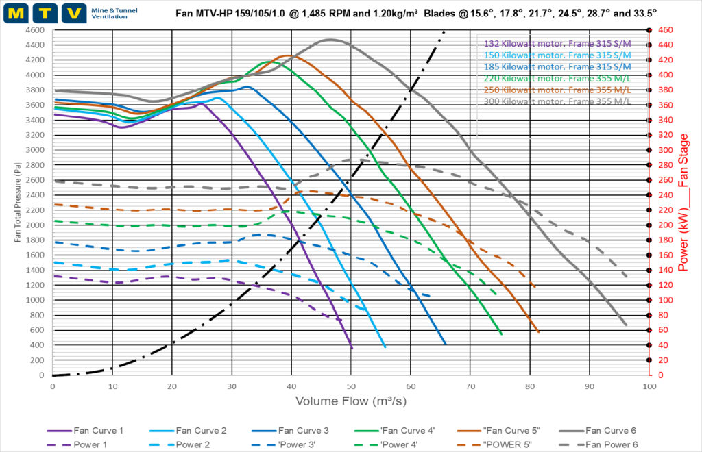
An air quantity of 60 m³/s has been measured in the fan inlet. At what pressure will the fan shown in the figure below with a blade angle of 33.5° operate and what is the expected shaft power?

Answer:
From the measured quantity, project a line vertically to where it intersects the Pressure curve. Project horizontally to the Pressure scale and from here the Fan Total Pressure can be extrapolated. In this case the Fan Total Pressure is 3800 Pa.
Similarly, the shaft power can be extrapolated from the measured quantity by projecting a line vertically to where it intersects the Power curve then horizontally to the Power scale where the Shaft Power can be extrapolated. In this case the Shaft Power is 280 kW.
An electrical motor could have an efficiency between 95% and 100%. If a motor efficiency of say 96% is applied, the absorbed electrical power is calculated:
Electrical Power = Shaft Power/Motor Efficiency
= 280 kW / 96 %
= 292 kW
To calculate the overall fan efficiency, the Air Power of the fan is required. The Air Power is calculated:
Air Power = Fan Total Pressure x Quantity / 1000
= 3800 Pa x 60 m³/s / 1000
= 228 kW
Fan Efficiency = Air Power (kW) / Shaft Power (kW) x 100
= 228 kW / 280 kW x 100
= 81.4 %
Overall Fan Efficiency = Air Power (kW) / Electrical Power (kW) x 100
= 228 kW / 292 kW x 100
= 78.1 %
It is important to understand what scales are included in the Fan Curve. It is also very important to ensure that if the fan curve is provided at standard density, the fan laws are applied to determine the correct values and to draw accurate conclusions from the fan curve.
The Fan Operating Point shown in the Fan Curve above is also used to determine the system resistance. The system resistance considers the losses incurred through the fan infrastructure such as the shock losses through the fan inlet screen, damper doors, diffusers, bends, fan silencers etc.
The system resistance is then calculated:
System Resistance (N.s²/m8) = (Mine Resistance Static Pressure (Pa) + Fan losses (Pa) ) / Quantity ²
= 3800 Pa / (60 m³/s)²
= 1.056 N.s²/m8
When applying Atkinson’s formula P = R.Q² a resistance curve can then be plotted against the quantities. The Fan Curve below illustrates the resistance curve:
If the system resistance is reduced, the fan will move more air through the system and if the system resistance is increased, the fan will move less air.
With variable blade angles and the fixed system resistance, it is also possible to determine how much air can be moved. For example if the blade angles are changed to 15.6°, based on the system resistance, the maximum flow the fan can move is only about 41.5 m³/s at a pressure of 1800 Pa.